Product Description:
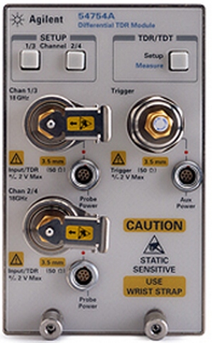
Agilent Technologies, Inc. 54754A Differential TDR module
The Agilent Technologies, Inc. 54754A oscilloscope is a graph-displaying device – it draws a graph of an electrical signal. In most applications, the graph shows how signals change over time: the vertical (Y) axis represents voltage and the horizontal (X) axis represents time. The intensity or brightness of the display is sometimes called the Z axis.
The Agilent Technologies, Inc. 54754A oscilloscope's simple graph can tell you many things about a signal, such as: the time and voltage values of a signal, the frequency of an oscillating signal, the “moving parts” of a circuit represented by the signal, the frequency with which a particular portion of the signal is occurring relative to, other portions, whether or not a malfunctioning component is distorting the signal, how much of a signal is direct current (DC) or alternating current (AC) and how much of the signal is noise and whether the noise is changing with time.
Key Features & Specifications
Two 18 GHz electrical channels with 3.5 mm (m) connectors
- Characteristic rms noise: 0.25 mV (12.4 GHz BW), 0.5 mV (18 GHz BW)
- Maximum input signal: 2 Vdc
- Two built-in step generators configurable for 1-port, 2-port common mode, or 2-port differential TDR or TDT measurements
- Built-in TDR/TDT calibration, user-selectable edge speed, S-Parameters (requires mainframe FW rev. A.06.01 or later. S-parameters requires option 202)
Compatibility
- 54750A High-Bandwidth Digitizing Oscilloscope Mainframe
- 83480A Digital Communications Analyzer Mainframe
- 86100A/B Infiniium DCA Mainframes
- 86100C Infiniium DCA-J Mainframe
- 86100D Infiniium DCA-X Mainframe
Accessories:
- Probing - refer to the "Description" section below for information on single-ended and differential TDR probes.
- TDR Calibration Kit - ensure measurement accuracy
- ESD Protection see Model 1202 from Picosecond ATE.
Description
The Agilent 54754A provides two 18-GHz channels that have built-in TDR step generators. The two channels may work in tandem to provide differential or common mode TDR stimulus/response, or may be used independently. Either channel works as a normal oscilloscope vertical system when the TDR/TDT step generators are not operating.
To protect your investment, you may want to consider using an ESD Protective device such as the one available from Picosecond ATE.
Probing And Calibration
Accurate probing of high-speed differential circuits can be a challenge. It is important to use a differential TDR probe with the correct bandwidth, pitch, signal configuration, etc. to match your design.
- N1021B 18 GHz Differential TDR/TDT Probe Kit
- N1024B TDR Calibration Kit
For compatible products and accessories see the Related Products tab
System configuration:
All 86100A/B/Cs and the 86100D in the ETR configuration have a internal trigger connections between modules and the mainframe. 86100Ds with option STR do not and therefore require an external cable (such as P/N 5062-6690) from the TDR modules trigger output to the mainframes trigger input. Use a power splitter (such as P/N 11667B) or divider (such as P/N 11636B) when using two TDR modules in an 86100D mainframe with option STR.

|
| Stock photo |